
|
[[stellae:wiki]]
|
EFIKA Power developers
 The EFIKA board is a very nice full featured system based around the MPC5200B SoC from Freescale.
The EFIKA board is a small size/low power device, but these nice features disappear immediately when you plug a standard CRT/TFT screen (at least 15”) and the power consumption dramatically drop when you plug one of these “modern” graphic cards.
That’s the reason why I’ve decided to apply to the EFIKA developer program for developing/studying low power/small sized display solutions for the EFIKA.
3D rules the world today but let’s take bbrv‘s words "the simple need still exists".
USB version
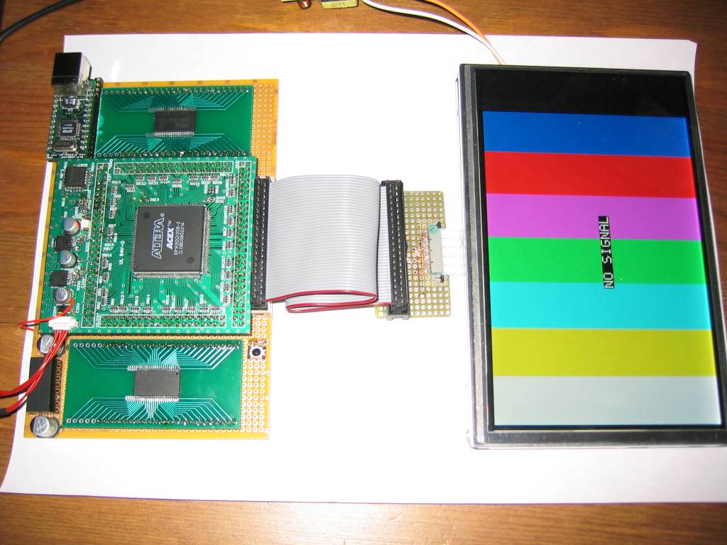
An early USB version of this “framebuffer” is almost ready. The VHDL code is under validation and a “userland” test application is almost ready. Stay tuned, the “v0.1a test version” will be quickly available.
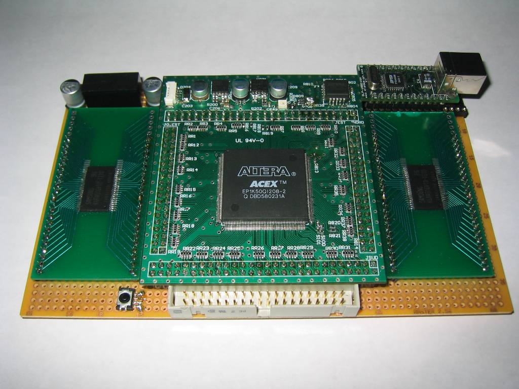
Schematics of the main FPGA board are available on a dedicated page.
You can see some pictures of the prototype below.
 |  |
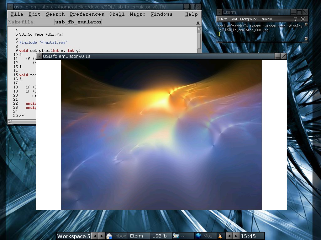
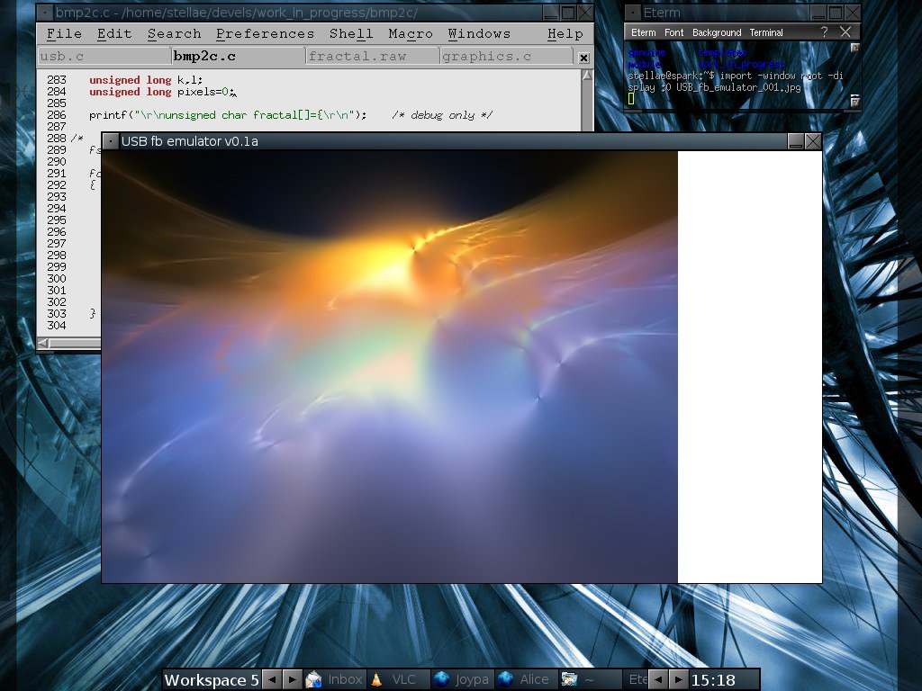
In order send pictures to the I/F, and simulate the result, I’ve written an quick and dirty emulator based on SDL. The program export 24bits MS Bitmaps to “raw” picture info and display them on a 16bits SDL surface (remember, we will use RGB 565 on the screen). In order to build the application, you will need the SDL libs installed on your computer.
The first picture on the emulator below is in RGB656, on the left, the genuine RGB24 picture. Differences can be seen on color gradients.
 |  |
The link with the EFIKA is USB at 11Mbps (same as the EFIKA), that the reason why only low resolution are targeted with this interface. This design is keep as simple as possible and do not use any proprietary IP cores.
Direct DVI interface for small size TFT panel
Small Wide VGA screens 1) (8”, 7” or smaller) are used today in the automotive market and can also be found in high-end mobile devices (Nokia 770 Internet Tablet, Archos AV704, ...). Some small monitors equipped with this kind of flat panel are available... but most of the time, they only have VGA connection and are very expensive.
In my opinion, digital TFT panels should always be driven by digital signals (eg. DVI) at their native resolution. Regarding the price and looking for DVI interface, I decided to build my own screen compatible with the EFIKA. Starting with a bare TFT panel, you will find here all the information you need to build the electronic board which will drive the panel.
For non-standard TFT interface, a DVI to RGB have to be used. The linux fb and the graphic card must output correct timings. Work is in progress. The first prototype of the DVI ⇒ RGB has been tested working on the EFIKA with an ATI radeon 9250 GPU. You can find below a bloc diagram of the electronic board driving an “OEM flat panel”.

On the software side, a custom EDID has been written. Nevertheless, I have also written a kernel patch for the fb_ddc.c file in order to test an EDID without programming it into the screen I²C memory (debug purpose).
Please don’t use this patch unless you perfectly know what you are doing.
To use this patch, copy the diff file into the root of the linux-2.6.19-rc6_efika linux distribution and apply the patch.
patch -p0 < fb_ddc.diff
This will add debug info in the “kernel log” and you will have the option to override your screen EDID. KERN_DEBUG message level is used. Here is an example of the debug output in dmesg:
Starting monitor auto detection...
radeonfb: I2C (port 1) ... not found
fb_ddc: EDID block found
0x   00 01 02 03 04 05 06 07 08 09 0a 0b 0c 0d 0e 0f
    ------------------------------------------------
00 | 00 ff ff ff ff ff ff 00 4e 85 01 00 01 00 00 00
10 | 01 11 01 03 80 0f 0a 00 0a 00 00 00 00 00 00 00
20 | 00 00 00 00 00 00 00 00 00 00 00 00 00 7f ff ff
30 | ff ff ff ff ff ff ff ff ff ff ff ff ff ff ff ff
40 | ff ff ff ff ff ff ff ff ff ff ff ff ff ff ff ff
50 | ff ff ff ff ff ff ff ff ff ff ff ff ff ff ff ff
60 | ff ff ff ff ff ff ff ff ff ff ff ff ff ff ff ff
70 | ff ff ff ff ff ff ff ff ff ff ff ff ff ff ff ff
fb_ddc: overriding screen edid
fb_ddc: EDID block found
0x   00 01 02 03 04 05 06 07 08 09 0a 0b 0c 0d 0e 0f
    ------------------------------------------------
00 | 00 ff ff ff ff ff ff 00 4e 85 01 00 01 00 00 00
10 | 01 11 01 03 80 0f 0a 00 0a 00 00 00 00 00 00 00
20 | 00 00 00 00 00 00 01 01 01 01 01 01 01 01 01 01
30 | 01 01 01 01 01 01 80 0c 20 d0 30 e0 2b 10 08 50
40 | 63 00 98 5c 00 00 00 18 00 00 00 10 00 00 00 00
50 | 00 00 00 00 00 00 00 00 00 00 00 00 00 10 00 00
60 | 00 00 00 00 00 00 00 00 00 00 00 00 00 00 00 10
70 | 00 00 00 00 00 00 00 00 00 00 00 00 00 00 00 aa
radeonfb: I2C (port 2) ... found TMDS panel
i2c_adapter i2c-2: unable to read EDID block.
i2c_adapter i2c-2: unable to read EDID block.
i2c_adapter i2c-2: unable to read EDID block.
radeonfb: I2C (port 3) ... not found
i2c_adapter i2c-3: unable to read EDID block.
i2c_adapter i2c-3: unable to read EDID block.
i2c_adapter i2c-3: unable to read EDID block.
radeonfb: I2C (port 4) ... not found
radeon_probe_OF_head
The EDID for my 7 inches (800*480) can be downloaded below. The Phoenix EDID Designer v1.3 software has been used to create the base file of this EDID. The development version of my ASCII EDID to Intel HEX-record convertion utility (DDC memory programming file) is also available.
mk_hex.sh is the script which transform Phoenix’s output files (*.dat) into an Intel HEX-record programming file compatible with most I²C memory programmers.
Usage: ./mk_hex.sh FILE

./mk_hex.sh ste0001_v1.0.dat
Here are some pictures of the “hardware” EDID memory patch, the home made EDID reader/programmer and a screenshot of the Phoenix EDID Designer v1.3.
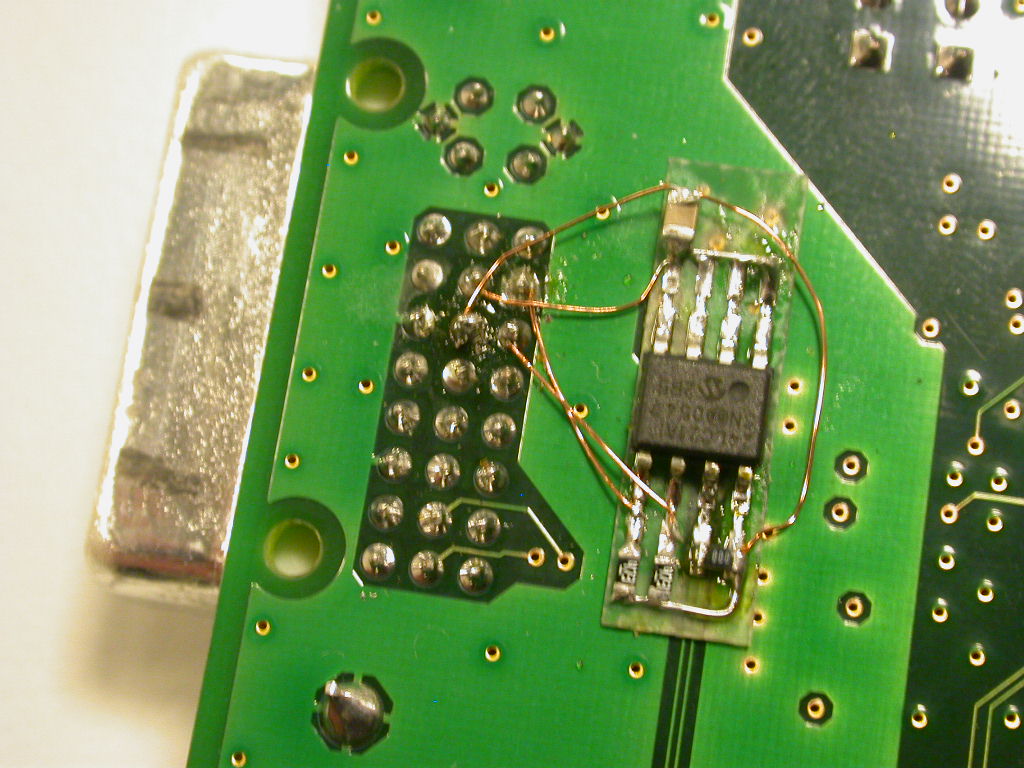 | 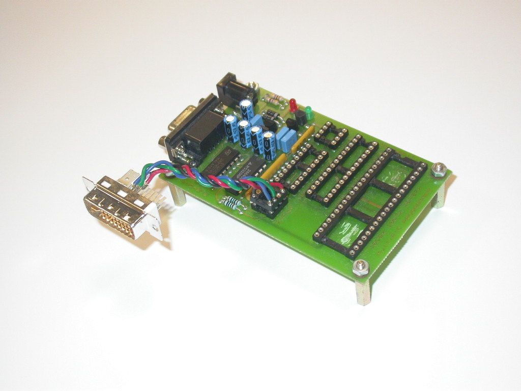 | 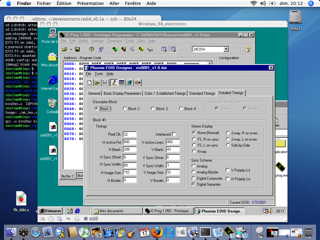 |
The design is based on a Texas Instruments TFP401A (TI PanelBus™ Digital Receiver) and use a Microchip 24LC21A memory for the EDID. You will find the datasheets in the “Related documentation” section.
Using an external programmer is not the only way to send the EDID info. inside the I²C memory. The eeprog program combined with the lm-sensors utilities package does this job very well.
First step: find which node corresponds to your DVI connector (all the following commands require root privileges).
tiny:~# i2cdetect -l
i2c-3   i2c             crt2                                    Algorithm unavailable
i2c-2   i2c             vga                                     Algorithm unavailable
i2c-1   i2c             dvi                                     Algorithm unavailable
i2c-0   i2c             monid                                   Algorithm unavailable
/dev/i2c-1 is the DVI connector. The mk_hex.sh script also generates a *.bin file which contains raw data for programming the memory with eeprog.
tiny:~# cat edid.bin | eeprog /dev/i2c-1 0x50 -f -w 0x00
eeprog 0.7.5, a 24Cxx EEPROM reader/writer
Copyright (c) 2003 by Stefano Barbato - All rights reserved.
  Bus: /dev/i2c-1, Address: 0x50, Mode: 8bit
  Writing stdin starting at address 0x0
................................................................................
................................................
The -f switch is mandatory since it suppresses a bug linked to a warning message displayed before programming (the getchar() at the end of this message “eats” the first byte coming from your *.bin file).
The content can be checked by reading back the EDID.
tiny:~# eeprog /dev/i2c-1 0x50 -f -x -r 0x00:128
eeprog 0.7.5, a 24Cxx EEPROM reader/writer
Copyright (c) 2003 by Stefano Barbato - All rights reserved.
  Bus: /dev/i2c-1, Address: 0x50, Mode: 8bit
  Reading 128 bytes from 0x0

 0000|  00 ff ff ff ff ff ff 00   4e 85 01 00 01 00 00 00
 0010|  01 11 01 03 80 0f 0a 00   0a 00 00 00 00 00 00 00
 0020|  00 00 00 00 00 00 01 01   01 01 01 01 01 01 01 01
 0030|  01 01 01 01 01 01 80 0c   20 d0 30 e0 2b 10 08 50
 0040|  63 00 98 5c 00 00 00 18   00 00 00 10 00 00 00 00
 0050|  00 00 00 00 00 00 00 00   00 00 00 00 00 10 00 00
 0060|  00 00 00 00 00 00 00 00   00 00 00 00 00 00 00 10
 0070|  00 00 00 00 00 00 00 00   00 00 00 00 00 00 00 aa
A precompiled static ppc version of eeprog is available just below. Note that the I²C subsystem and all related modules must be enabled in the kernel (and loaded if necessary) to use this program. Using this tool on the EFIKA is quite safe since the only I²C channels are on the GFX. Nevertheless, read all the warnings before using this tool.
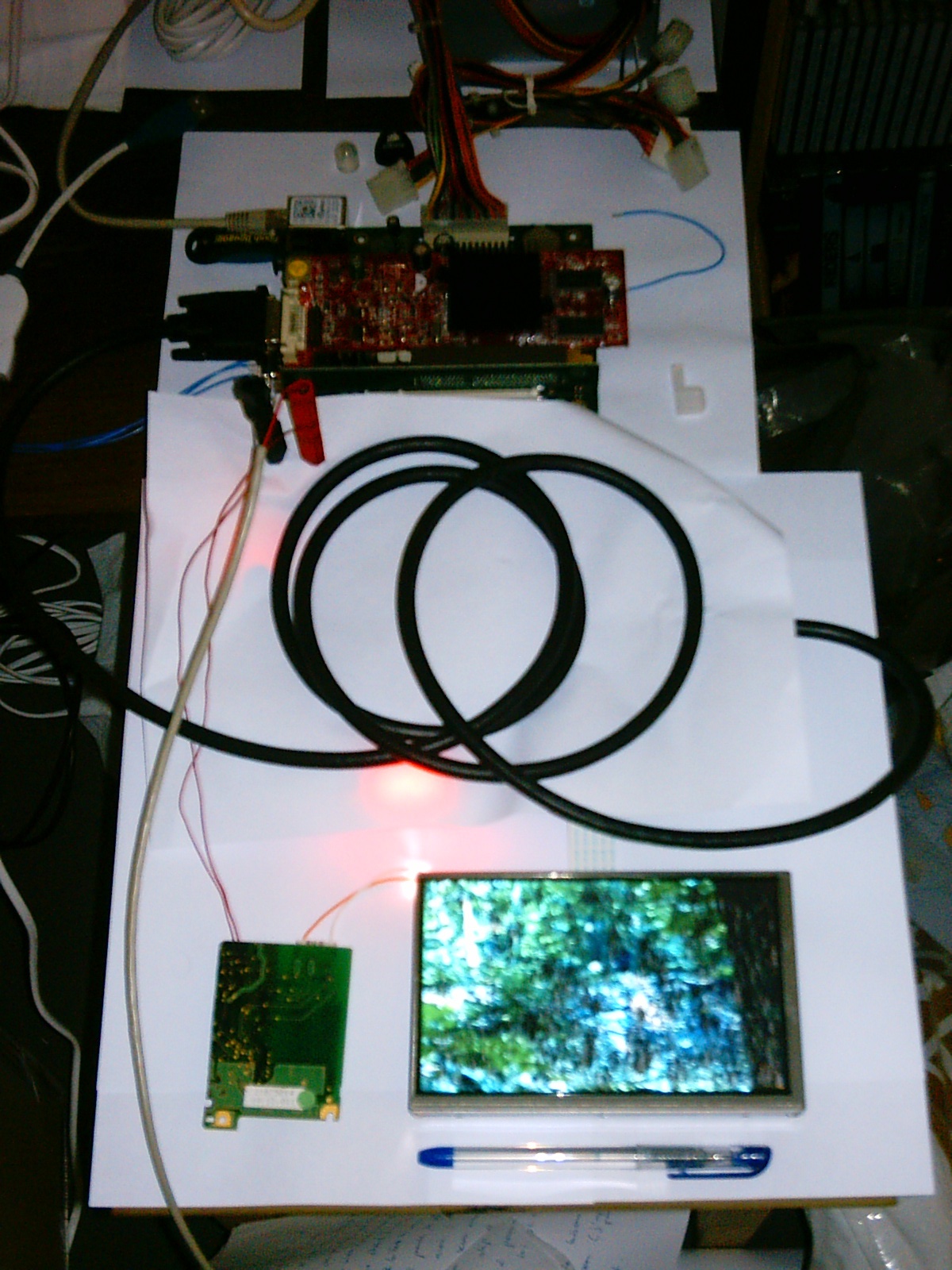
Picture of the EFIKA at work. Note that on the pictures the board is voluntarily hidden because the current design includes non “open-source” parts. But be assured that the free version is currently under development.
To get optimal performances with the EFIKA, I’ve set Directfb and also SDL which uses Directfb as video driver.
I do apologize for the bad quality of the pictures...
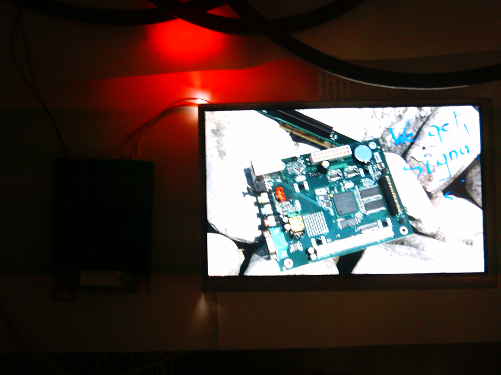 |  |
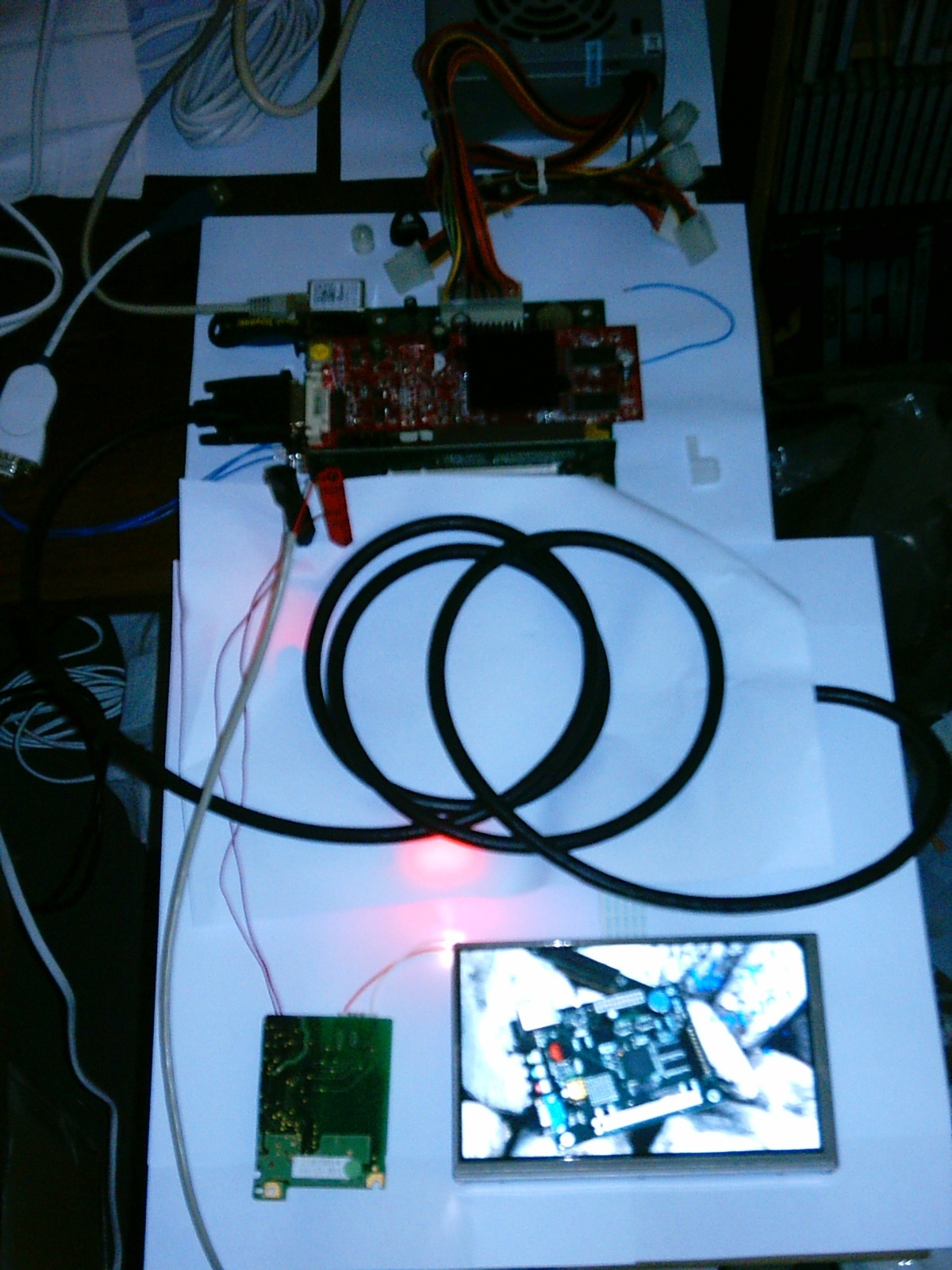
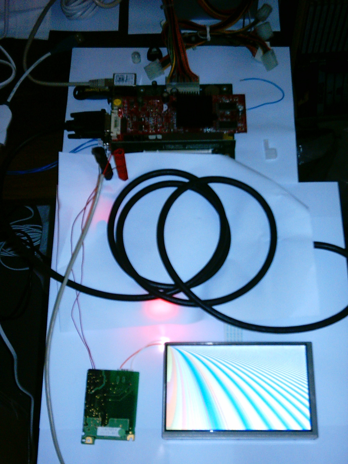
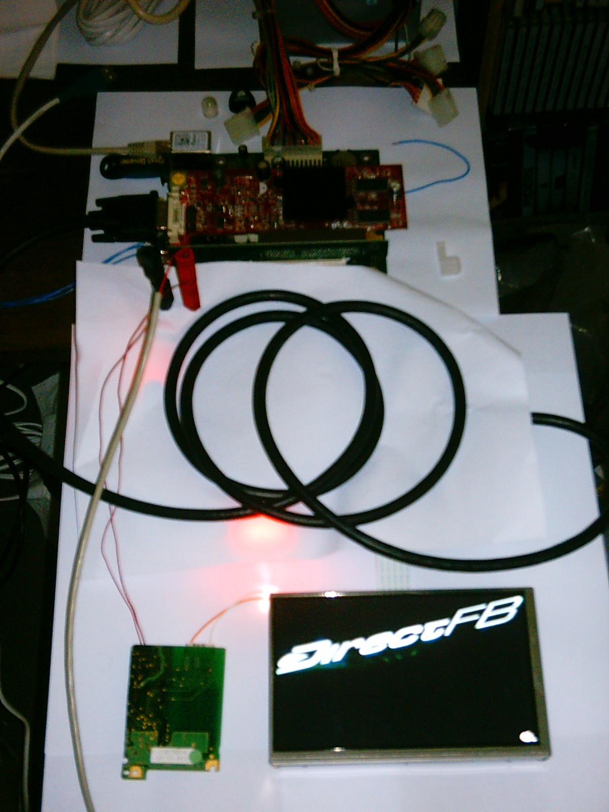
And the whole system.
 |  |  |  |
I’ve also made several small videos of the board start sequence, basic Directfb and SDL demos.
xorg (X11R7) configuration
Since I don’t want to install xorg on the EFIKA for the moment (Directfb has all the features I need and is very lite), the screen has been tested with xorg on a (x86) desktop computer with the same 9250 Radeon gpu board as above. The behaviour of xorg described here will be the same on the EFIKA.
If you use a flat panel with xorg, the timings send to the screen will be those found in the screen EDID by default. Even if the resolution you’ve set for the window manager/desktop is not the native resolution of the screen, the picture will be “artificially” scaled by the graphics card. This means for example that the pixel clock will remain constant (i.e. ~108Mhz for a standard SXGA (1280*1024) screen).
If you want to override this feature and send exactly the timings specified in the “Modeline”, you have to use the following parameter in the “Device” section.
Please be very carefull if you use this feature.
Option "IgnoreEDID" "true"
This option was very useful for testing my WVGA screen modeline parameters before writing a custom EDID (I started X with an SXGA screen to activate the DVI out and then switched to the 7” screen. Note that the HP screen (flat panel) I’ve used for this test supports the WVGA timings...
Only for reference, I put here the correct modeline used to drive the WVGA screen (native resolution timings).
ModeLine "800x480" 31.104 800 824 904 1008 480 486 489 523 -hsync -vsync
Here is the (dirty) xorg.conf file I’ve used. (skeleton coming from the default Knoppix xorg.conf)
And some pictures of the KDE desktop displayed on the screen (taken with a better camera this time...).
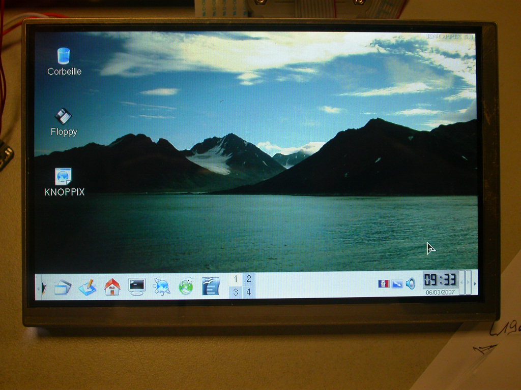 | 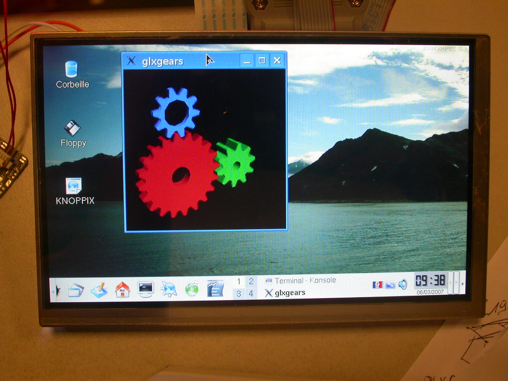 |
Despite of its small size, this screen remains perfectly usable with a window manager. Small one such as Fluxbox (shown in my SUN Ultra5 presentation), WindowMaker, IceWM... could be fine.
Schematics
This is a preliminary version of the I/F schematics.
Related documentation
DDWG & VESA
Datasheets
Project's Blog
Many thanks Genesi & bplan for providing the EFIKA board used in this project.
Stay tuned on the Project 337 blog.
Stellae (N. Lemouël) January, 21st 2007 website@stellae.fr
DDC is a Trademark of VESA (Video Electronics Standard Association)